Solar Energy Concepts earns commission from qualifying purchases via links on this page.
TL;DR Solved by splitting CAN and RS-485 using a single network cable. Jump to the solution:
If you are still choosing the Pi, cable and first connection path, use the Solar Assistant setup guide first. This page owns the shared-port CRC repair once the basic path is selected.
Why Does this Problem Happen And Who Is Affected
Usually, Solar Assistant runs on a Raspberry Pi computer near the inverter. You can connect the PI to the inverter using RS-485 or via WiFi.

If you have a battery connected to your inverter, chances are the battery’s communication cable is plugged in the inverters RS-485/CAN port. If your inverter, uses a single RJ45 port for both RS-485 and CAN protocols, like the Sunsynk 3.6, this means that if you want to connect solar assistant too then you’re out of ports. The good news is that you can use a single cable in a single port and still utilize both protocols. This is because they can operate independently of each other on the RJ45 crimped cat 5 cable.
Once you solve the CRC error, you can even explore advanced SolarAssistant rules to force grid export and prevent battery waste. But first, here’s how solar assistant’s help materials show this on a diagram:

CRC Error When Connecting Sunsynk Inverter To Solar Assistant
This error usually happens because of signal mixup. The common culprit here is a network cable splitter.
You can use such splitters to keep the battery and Solar Assistant connected to the inverter at the same time. But splitting the signals is not trivial and you can end up wasting money on various cables until you have a working solution.
Here is a solution that requires no splitter and no expensive cables. A single network cable, cat 5 is good enough, connected to the CAN/RS-485 port of the inverter on one side and modified on the battery side. Here is what you need to do:
- Isolate CAN from RS-485 – only the battery needs the CAN
- Carefully cut and open up a section of the cable’s outer sheath to gain access to the wire pairs inside it.
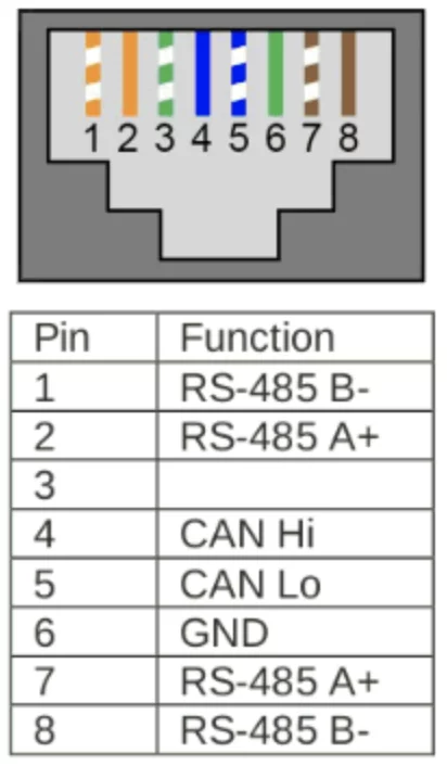
- The wires connected to pins 4 and 5 are the pins handling CAN, remain connected to RJ45 jack, and it is inserted in the CAN port of the battery. Likely these are the white-and-blue and solid-blue wires.
- The rest of the wire pairs are disconnected from the RJ45, cutting them is a good way to do that.
- Connect RS-485 to the Raspberry pi
- Identify the wires connected to pins 1 and 2 from the RJ45. Likely these are the white-and-orange and solid-orange wires.

- Take these wires and connect them to an RS-485 to USB adapter, effectively making your cable — the adapter used in the image simpler than the other suggested one but works too. From here, you will see the new USB connection in Solar Assistant’s settings and proceed to connect.
 DIY Splitting the CAN and RS-485 wires from a cat-5 cable.The RS-485 wires go into a USB terminal and into the Raspberry Pi
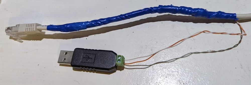 DIY Splitting the CAN and RS-485 wires from a cat-5 cable.
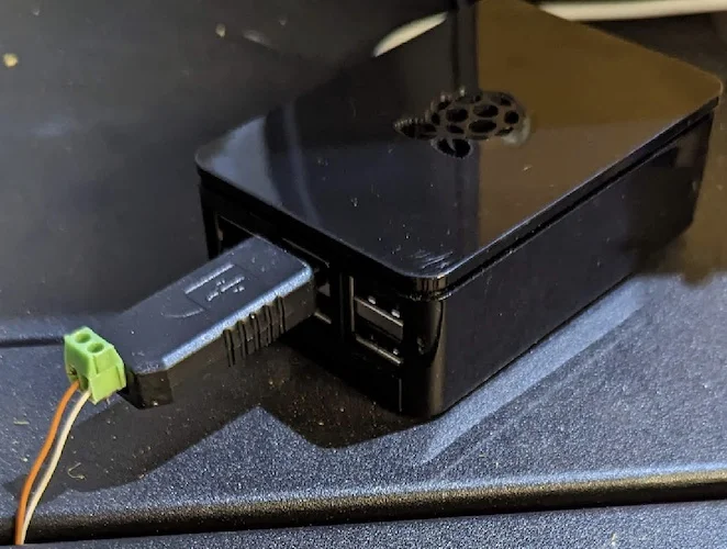 The RS-485 wires go into a USB terminal and into the Raspberry Pi