
A Sunsynk or Deye setting rarely acts alone. The result you see is usually controlled by the active operating mode, the current timer row, its SOC and Power values, the inverter current limits, the battery management system (BMS), and the protection thresholds. The useful question is not simply “what should this setting be?” It is “which control is limiting the system right now?”
This guide explains that interaction. It does not give you a universal set of percentages to copy. A setting that suits my Sunsynk 3.6 ECCO, Fogstar battery bank and tariff can be wrong for a different battery, inverter family, wiring arrangement or grid code.
Go straight to the setting problem you have:
- For overnight grid charging, check the permission chain first: confirm the model-specific enable, row and SOC conditions before changing current.
- Solar charging above row SOC is often expected: on the cited Sunsynk path, surplus PV is not hard-capped by timer SOC.
- To preserve backup energy, coordinate row SOC with Low Batt: never lower Low Batt, Shutdown or Restart to make a schedule work.
Coverage of this guide
SEC’s owner review records my inverter as a Sunsynk 3.6 ECCO family model. The exact suffix and firmware version have not been captured for this guide. Separately, my Solar Assistant screenshot proves that a particular schedule was stored on my system. It does not prove the inverter suffix, firmware or family-wide behaviour, so the image will remain out of the published article until its caption provenance is complete.
The Deye examples are manual-based. They include the low-voltage, single-phase SUN-3.6-6K-SG03LP1-EU family in Deye’s February 2024 manual and, where stated, the SUN-12/14/16K-SG01LP1-EU-AM3-P family. I have not tested a Deye inverter on my own system.
This guide does not verify Deye or Sunsynk high-voltage, three-phase, US split-phase or every regional model. Check the rating label, exact manual and interface before transferring a label or behaviour.
| Source and interface | Claims used here |
|---|---|
| Sunsynk Classic/Acure/Elite portal support interface | Work modes, Use Timer, timer examples, timer Power and Priority Load/Priority Battery |
| Sunsynk Classic/Elite Basic Set-Up Guide | The source-selected timer SOC examples stated under that exact scope |
| Sunsynk’s current Avoiding Conflicts support timer | Timer 1 to Timer 6 order and the Timer 6 midnight rule |
| Deye SUN-3.6-6K-SG03LP1-EU, February 2024 manual | Battery current fields and protection, work modes and Time of Use on printed pages 28 to 31 |
| Deye SUN-12/14/16K-SG01LP1-EU-AM3-P manual | The separately labelled Grid Charge and Energy Pattern precedence example |
Start with the power-flow model
An inverter has several possible sources and destinations for energy. Solar can supply the house, charge the battery or export. The battery can supply the house and, on some configured systems, export. The grid can supply the house and may charge the battery when both the model and settings permit it.
The settings decide which of those paths are allowed. The limits decide how much power may use an allowed path. Protection controls can stop a path even when the operating mode and timer appear to permit it.
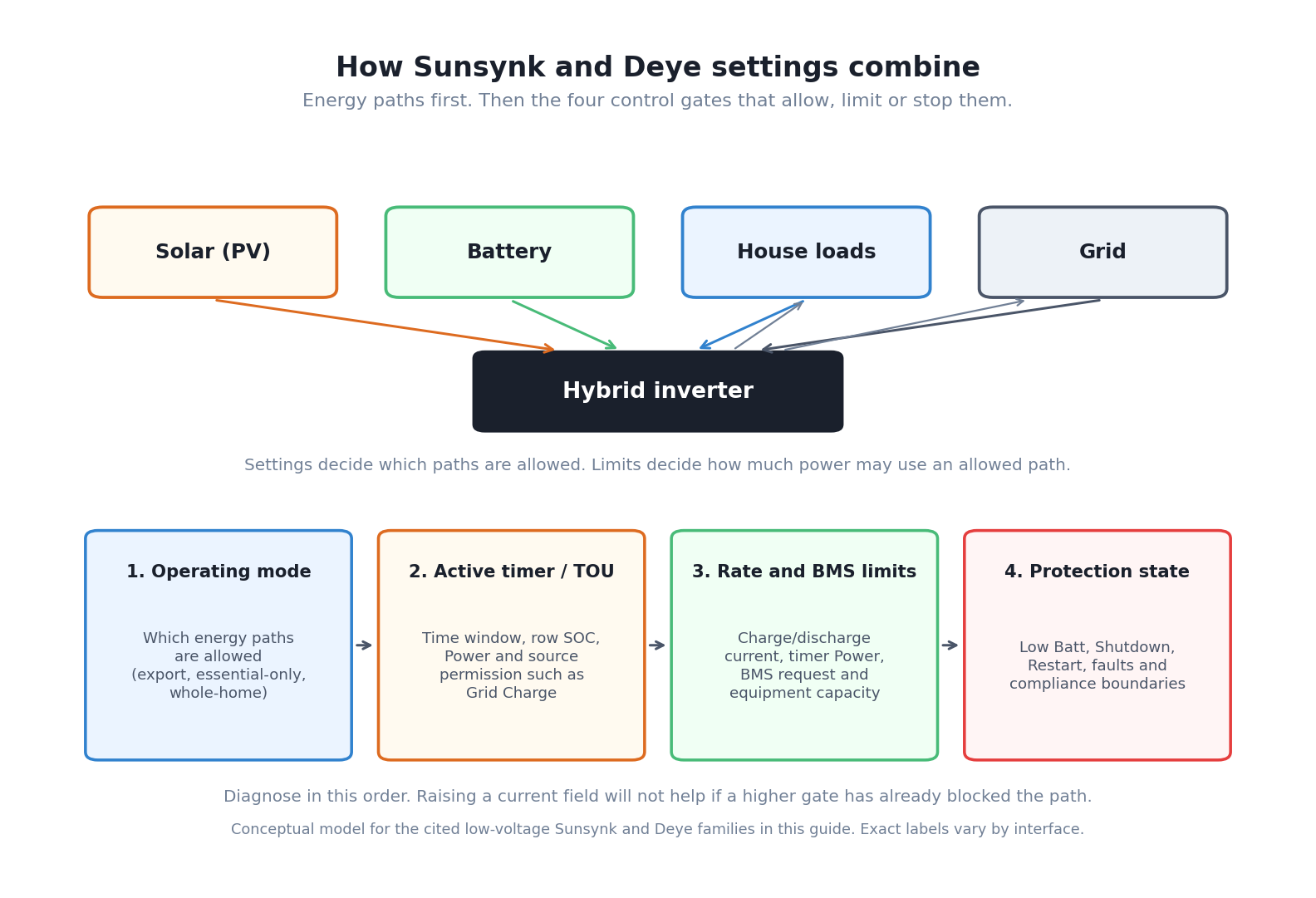
That gives you four questions to ask in order:
- Which energy path does the operating mode allow?
- What does the active timer row request or protect now?
- Which power, current or BMS limit constrains that request?
- Has a protection threshold or fault stopped it?
This order prevents a common mistake: raising a current field because a battery is not charging when the real cause is a missing source permission, a timer SOC below the current SOC, a BMS request of 0 A or a protection condition.
A consequence map, not a universal label map
Sunsynk and Deye share some control concepts across compared low-voltage models, but similar labels do not prove identical behaviour. Use the table as a navigation aid, then read the model-scoped explanation below it.
| Control concept | Labels you may encounter | What it changes | What it does not prove |
|---|---|---|---|
| Operating priority | Work Mode, Selling First, Zero Export to Load, Zero Export to CT | Which power paths are available and which loads can be served | That two models use the same priority order |
| Scheduled operation | System Mode Timer, Time of Use, Use Timer | The active time window, permitted source and battery policy | That the SOC number is always a charging target |
| Source permission | Grid Charge | Whether the grid may charge the battery in the relevant conditions | That charging must start or reach the requested SOC |
| Solar priority | Priority Load, Priority Battery, Energy Pattern | Whether available solar serves loads or the battery first | That the timer SOC caps solar charging |
| Battery rate | Sunsynk Charge Amps, Grid Amps or Discharge Amps; Deye Max A Charge, Max A Discharge or grid-charge A; timer Power where documented | An overall, source-specific or directional limit according to the named field | That the battery or BMS will accept it |
| Battery protection | Low Batt, Shutdown, Restart, BMS limits | Conditions that protect or recover the battery | Extra usable capacity that can safely be exposed |
The full cross-brand capability comparison belongs in SEC’s Sunsynk versus Deye capabilities guide. This page owns the operational question: how do the active controls combine to produce the result you see?
What the operating modes change
An operating mode is the first gate. It decides whether the inverter may export and which connected loads it may support. The exact consequence depends on the model and metering arrangement.
Sunsynk Classic/Acure/Elite portal consequences
In Sunsynk’s current System Mode support interface:
- Selling First allows surplus power to be sold to the grid under the documented conditions.
- Zero Export with Limit to Load only selected restricts the inverter’s output to the backup or essential load side.
- Limited to Home uses the external meter or CT point so inverter power can also support home loads outside the backup output while limiting export.
These statements explain allowed power paths only. They do not tell you which mode to choose or prove that zero export is working. CT setup, meter verification, trickle tuning and unwanted-export diagnosis belong in the dedicated zero-export guide.
Deye SG03 consequences
On the SUN-3.6-6K-SG03LP1-EU family, Deye’s February 2024 manual, section 5.7 on printed pages 30 to 31, separates three consequences:
- Selling First permits surplus power to be sold under the documented settings.
- Zero Export to Load serves the backup load connection.
- Zero Export to CT can serve the backup and on-grid home loads when the required external CT is used.
Solar Sell is a separate surplus-export permission. It does not change which load connection Zero Export to Load serves. These definitions remain specific to SG03.
If your question is how to select, configure and meter a zero-export mode, that needs a separate end-to-end test. This guide only establishes that the operating mode can allow or block the energy path before the timer and battery limits are considered.
How the timer and Time of Use work
The timer divides the day into operating windows. Each active row combines a time boundary with controls such as Power, SOC and permission to charge from the grid. Read it as one conditional instruction, not a group of independent settings.
In Sunsynk’s current Avoiding Conflicts support timer, the six rows must remain in chronological order. That source says only Timer 6 may roll across midnight into Timer 1. Its documented cheap-rate example uses Timer 6 before midnight and Timer 1 after midnight to cover one continuous overnight period. This rule is scoped to that support timer, not every Sunsynk product or firmware.
Do not apply that sequence blindly to a different Deye family, an older LCD or another app. Confirm how the exact interface represents the start and end of a period. A timer that looks correct in an app can still be different from the schedule stored by the inverter.
Timer SOC is a floor or a charging level depending on the conditions
If your battery charges above the timer SOC in sunshine, that is often expected on the cited Sunsynk path: the row SOC does not hard-cap surplus PV, while selecting Grid Charge changes the same number into the level grid charging works towards overnight.
The SOC number in a Sunsynk timer row is often described as a target. That description is incomplete.
For the Sunsynk Classic/Elite setup path and compatible examples in Sunsynk’s current support material:
- With Grid Charge selected and the grid available, the grid may charge the battery towards the row SOC.
- Without Grid Charge selected, the battery may discharge towards the row SOC while the grid is present.
- Surplus solar may charge the battery above the row SOC. The row value is not a universal maximum solar SOC.
- The result still depends on the operating mode, Priority Load or Priority Battery, rate limits, BMS requests and protection controls.
The table below shows the practical interpretation. It deliberately says “may” because permission is not a guarantee that another limit will allow the requested power.
| Active row state | Actual battery SOC | What the row permits or protects | Important qualification |
|---|---|---|---|
| Grid Charge selected and grid present | Below row SOC | Grid charging towards the row SOC | Charging can be restricted by timer Power, current limits, BMS allowance and available grid power |
| Grid Charge selected and grid present | At or above row SOC | No grid charging solely to push beyond the row SOC | Solar may still charge above it |
| Grid Charge not selected | Above row SOC | Battery discharge towards the row SOC may be allowed | Loads, operating priority and other limits still determine actual discharge |
| Grid Charge not selected | Below row SOC | The row does not grant grid recovery | Low Batt, battery protection and available solar become important |
| Surplus solar available | At or above row SOC | Solar charging may continue | Priority settings and the battery’s permitted charge rate still apply |
This is why two owners can use the same 50% row and report different behaviour. One has selected Grid Charge and starts below 50%. The other has not selected it and starts above 50%. The number is the same, but the condition is different.
How the Deye SG03 Time of Use row differs
Deye’s SG03 manual gives a parallel conditional example in section 5.7, printed page 31. Time of Use is the master enable for the schedule. Only when it is enabled do the row’s Grid, Batt SOC, time and Power fields take effect. With Grid selected for an active row, the grid can charge the battery up to that row’s Batt value under the documented conditions. Without source charging, the battery can discharge towards the row’s Batt value.
One difference matters when diagnosing power. The SG03 manual describes the row’s Power as maximum battery discharge power. Sunsynk’s cited portal support describes its timer Power as a maximum for battery charge or discharge. Do not use a Deye SG03 row Power value as though the manual had defined it as a grid-charge ceiling.
Priority Load and Priority Battery change where solar goes
For the Sunsynk Classic/Acure/Elite portal support interface, solar allocation and timer policy are separate decisions:
| Active Sunsynk condition | Documented consequence | Useful diagnostic |
|---|---|---|
| Priority Load with ordinary surplus solar | Solar serves the load before the battery | Compare PV, load and battery flow before changing the row SOC |
| Priority Load with a 100% row SOC | The battery can be held at 100% through that period | A high row SOC can explain an apparently reluctant discharge |
| Priority Battery during its selected period | Solar is directed to the battery first, subject to the configured PV Charge Amps and other limits | Strong PV can coincide with reduced PV-to-load flow or grid import |
| After the selected Priority Battery period | The ordinary active mode and timer policy resume | Check the active row before treating the change as a fault |
This table is not a Deye crosswalk. It is a consequence map for the cited Sunsynk portal support interface.
Deye also documents an interaction between source permission and priority, but only for specific families. On the SUN-12/14/16K-SG01LP1-EU-AM3-P, enabling Grid Charge forces Load First and makes the selected Energy Pattern inactive. This is a concrete case where one setting overrides another. It should not be assumed on another Deye or Sunsynk model without its manual.
Find the binding constraint
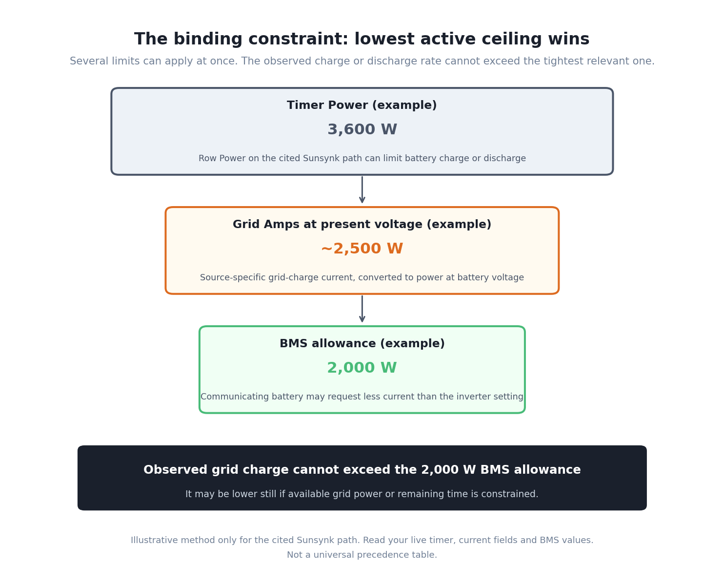
The timer can permit charging and the battery can still miss the row SOC. Several constraints act at the same time, and the most restrictive relevant one governs the observed rate. There is no universal count or precedence chain.
| Common constraint | Sunsynk field in the cited support interface | Deye SG03 field | How it can restrict the result |
|---|---|---|---|
| Timer power | Power, documented for battery charge and discharge | Power, documented as maximum battery discharge power | Restricts only the direction defined by that named source |
| PV charge current | Charge Amps | No separate PV-only equivalent established here | Caps the Sunsynk inverter’s requested PV battery-charge current |
| Overall battery charge current | Check the applicable source field and equipment limits | Max A Charge | Sets the SG03 maximum battery charge current across charging sources |
| Grid charge current | Grid Amps | Separate grid-charge A field | Sets the source-specific requested battery current from the grid; on SG03 it also remains subject to Max A Charge |
| Discharge current | Discharge Amps | Max A Discharge | Caps requested battery discharge current |
| BMS request | Visible charge or discharge allowance, where exposed | Visible charge or discharge allowance, where exposed | A communicating battery may ask the inverter to reduce or stop current |
| Equipment and protection | Inverter, battery, temperature, voltage, cables, fuses and protection state | Same categories, checked against SG03 and battery documentation | A schedule cannot override an equipment or safety boundary |
| Available energy, load and time | Solar, grid allowance, house demand, battery voltage and time remaining | Same physical quantities | The source may be insufficient or the window too short |
Current and power are related, but they are not interchangeable. At a simple level, battery power is approximately battery voltage multiplied by current. A 50 A setting on a low-voltage battery does not represent the same power as 50 A on a high-voltage battery. Losses and control margins also mean the observed AC and DC values will not be identical.
Suppose grid charging on the cited Sunsynk path has a timer Power of 3,600 W, Grid Amps equating to roughly 2,500 W at the present battery voltage, and a BMS allowance equating to 2,000 W. The observed grid charge cannot exceed the 2,000 W BMS allowance. It may be lower if available grid power or the remaining time is constrained.
That example explains the method, not a universal precedence chain. Use the actual values visible on your inverter and BMS. Do not increase a battery current setting merely to make the timer complete faster.
Follow the Sunsynk grid-charge permission chain
A cheap-rate window is only one part of the current Sunsynk Classic/Acure/Elite portal support path. Check the controls your exact interface exposes in this order:
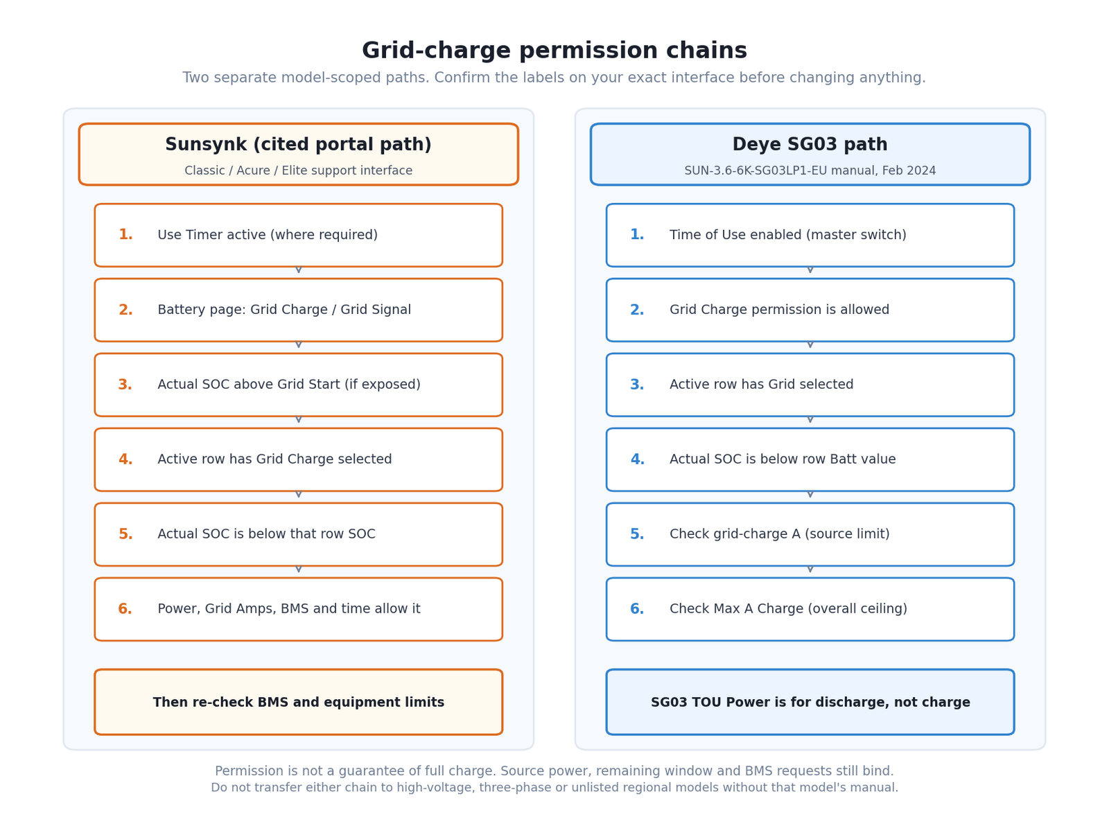
- Use Timer is active where the support interface requires it.
- The battery page permits grid charging through Grid Charge and the corresponding Grid Signal control where exposed.
- Battery SOC is above Grid Start where that setting is exposed. On the cited support path, grid charging begins only above Grid Start. Do not move the percentage without checking Low Batt, Shutdown and the exact instructions.
- Grid Charge is selected in the active timer row.
- Actual SOC is below that row’s SOC.
- The row’s Power, Grid Amps, BMS allowance, equipment protection, available grid power and remaining time are sufficient.
Not every Sunsynk interface exposes every label in this form. A battery may charge correctly but still stop short because the permitted power multiplied by the remaining time is not enough to add the required energy. House demand, conversion losses and a falling BMS allowance near high SOC can widen the gap.
The Deye SG03 grid-charge path
On Deye SUN-3.6-6K-SG03LP1-EU, Time of Use must first be enabled before the scheduled row’s Grid, Batt SOC, time and Power fields take effect. Section 5.6 on printed pages 28 to 29 documents Grid Charge permission, Max A Charge as the overall maximum battery charge current and a separate grid-charge A field for the grid source. Section 5.7 on printed page 31 shows the row fields. During grid charge, inspect both Max A Charge and grid-charge A, then the actual SOC, BMS allowance, protection state, available power and time. SG03 TOU Power is documented for discharge, so it should not be inserted into the grid-charge calculation as a charge ceiling.
On my own Sunsynk and Fogstar system, Solar Assistant records a configuration that allows grid charging from 00:30 to 05:30 towards 90% SOC. SEC’s owner review records the inverter family as a Sunsynk 3.6 ECCO. The configuration capture does not prove the exact suffix, firmware or a controlled result showing that every charge reaches 90%.
The dedicated Fogstar owner review contains the battery-specific observations. Detailed tariff automation belongs in the Solar Assistant automation guide rather than here.
Row SOC, Low Batt, Shutdown and Restart are different
The active timer row answers a scheduling question. Low Batt, Shutdown and Restart answer protection and recovery questions. Treating them as spare versions of the same SOC setting can produce confusing or unsafe changes.
Sunsynk’s current battery troubleshooting guidance says the System Mode SOC values must be coordinated with Low Batt. A timer row below Low Batt can request behaviour that the battery protection settings do not permit. Sunsynk’s battery guidance also treats Shutdown, Low Batt and Restart as separate controls.
The exact sequence and available labels vary with the model, battery type and whether the battery communicates by CAN or RS485. Do not lower a protection threshold to expose more capacity unless the battery manufacturer, inverter compatibility information and installer design all support it.
The same restraint applies to BMS limits. A communicating battery may report a permitted charge or discharge current. The inverter can display a larger configured maximum while delivering less because the battery has reduced its request due to SOC, temperature, voltage or an internal protection condition.
If the inverter and BMS disagree about battery voltage, stop treating it as a timer problem. Sunsynk documents a safety response when its inverter-side and BMS voltage readings differ materially. That needs protocol, battery and support checks, not a higher charge setting.
On Deye SG03, section 5.6 on printed pages 28 to 29 documents Shutdown, Low Batt and Restart separately alongside Max A Charge, Max A Discharge and grid-charge controls. Their presence supports the same diagnostic distinction for that family, but not the transfer of a Sunsynk value or sequence. Use the battery and SG03 documentation together.
Why apparently correct settings conflict
Most settings problems become clearer when you translate the symptom into the first gate that could cause it.
| What you see | Check first | Then check | Do not assume |
|---|---|---|---|
| Battery does not grid charge on the cited Sunsynk path | Use Timer, battery-page permissions, active-row Grid Charge and actual SOC above Grid Start where exposed | Grid Amps, timer Power, BMS allowance, Low Batt, available power and time | That PV Charge Amps is the relevant field |
| Deye SG03 battery does not grid charge | Time of Use enable, Grid Charge permission, active-row Grid selection, actual SOC and row Batt value | Grid-charge A as the source-specific setting, Max A Charge as the overall ceiling, BMS allowance, protection, available power and time | That SG03 TOU Power is a grid-charge ceiling |
| Battery charges more slowly than expected | The source-specific current field and observed battery voltage/current | Applicable timer Power, BMS request, house demand, source allowance and temperature | That the timer row is being ignored |
| Battery stops near the row SOC | Source selection and actual active row | Whether surplus solar is available and which priority is active | That the row SOC is a universal maximum |
| Battery charges above the row SOC | Solar flow and Priority Load/Priority Battery | Other charge permissions and BMS limits | That Grid Charge has failed |
| Battery discharges when grid is present | Grid box clear, actual SOC above row SOC and operating mode | Sunsynk Discharge Amps or Deye Max A Discharge, applicable TOU Power and load demand | That the timer SOC should force charging |
| Strong PV but unexpected grid import or reduced PV-to-load flow on the cited Sunsynk interface | Priority Load/Priority Battery, active row and row SOC | PV Charge Amps, battery demand and the end of the selected priority period | That the CT or solar array has failed |
| Setting changes back | Compare the inverter, portal and any local automation | Confirm whether a known controller is writing the value | That every interface has an audit log |
| Charge or discharge stops with a warning | Visible fault, BMS request and inverter-versus-BMS voltage | Battery protocol, firmware and manufacturer support | That changing the timer will clear it |
Remote control adds another possible instruction. I use Solar Assistant with my Sunsynk system, so I check its active automations as well as the inverter timer. That is a first-hand reason to inspect both interfaces, but it does not prove a universal write order between every app, portal and inverter firmware.
A safe diagnostic order
Change one thing only after you have recorded the current state. A photograph or screenshot of every relevant page gives you a restoration point and stops one test becoming six untraceable changes.
- Confirm that scheduling is enabled, then identify the active row. Record Use Timer on the cited Sunsynk path or Time of Use on Deye SG03. Then record the row’s time, SOC or Batt value, Power and source selections.
- Compare requested and actual SOC. Note actual SOC, row SOC and Low Batt without changing any of them. On the cited Sunsynk path, confirm actual SOC is above Grid Start where that setting is exposed.
- Compare the relevant rate controls. For Sunsynk, record PV Charge Amps, Grid Amps or Discharge Amps according to the active source, plus timer Power. For Deye SG03 grid charging, record both grid-charge A as the source-specific setting and Max A Charge as the overall battery-charge ceiling. For SG03 discharge, record Max A Discharge and TOU Power. Add any BMS-reported allowance.
- Check the energy path. Record the operating mode and, on supported Sunsynk interfaces, Priority Load or Priority Battery.
- Check known remote control. Pause only an automation you understand and can restore. Do not assume the portal provides a change log.
- Check visible health data. Record inverter voltage, BMS voltage, temperature and any fault code.
- Escalate the unsafe layer. Firmware, battery protocol, protection, CT wiring and grid-code changes belong with the manufacturer or a competent installer.
Observe the system through a complete short interval after a benign change. The immediate screen value can be misleading because loads, solar and BMS requests are moving at the same time.
Three settings recipes, without copying my numbers
A useful recipe defines the purpose and the relationships between controls. It does not prescribe the same SOC or current to every battery.
Here, backup reserve means energy you intentionally retain for a later interruption. It is ordinary-language shorthand, not a universal Sunsynk or Deye menu label. On every recipe below, keep timer SOC coordinated with Low Batt and the supported protection order. Never lower Low Batt, Shutdown or Restart merely to make a schedule work.
Maximise direct solar self-consumption
- Select an operating mode that allows solar to serve the intended household loads.
- Use the timer to permit battery discharge only to the energy you intend to retain, while keeping every row SOC at or above the supported Low Batt relationship.
- On the cited Sunsynk interface, choose Priority Load or Priority Battery according to whether immediate household demand or battery charging should receive solar first, and check PV Charge Amps rather than Grid Amps for this solar-charging path.
- Keep export control and CT commissioning in the separate zero-export procedure.
The result should be checked at the physical import/export meter as well as the inverter display. This article does not teach CT placement or zero-export commissioning.
Charge during a cheaper tariff window
- Follow the exact model’s grid-charge permission path. For the cited Sunsynk interface this includes the relevant battery-page permissions, actual SOC above Grid Start where exposed and the active row. On Deye SG03, enable Time of Use before relying on the row fields, then check Grid Charge and the row’s Grid selection.
- Set the row SOC from the energy you need, not from someone else’s screenshot, and keep it coordinated with Low Batt. Never lower Low Batt, Shutdown or Restart to force the schedule.
- Confirm the relevant source-specific current, BMS and equipment allowances can add that energy within the cheap period. On Sunsynk, inspect Grid Amps and timer Power. On Deye SG03, inspect grid-charge A as the grid-source setting and Max A Charge as the overall battery-charge ceiling. Do not use SG03 TOU Power as a charging limit.
- Split an overnight period according to the exact interface. In Sunsynk’s current Avoiding Conflicts support timer, only Timer 6 rolls across midnight into Timer 1.
- Record whether another controller, such as Solar Assistant, is changing the same values.
My 00:30 to 05:30 and 90% configuration is one tariff-led example. It is not a recommendation for your battery.
Preserve a modest backup reserve
- Choose a row SOC that leaves the backup reserve you have decided to preserve during normal grid-present operation.
- Keep it coordinated with Low Batt and the battery manufacturer’s protection requirements.
- Make sure discharge power is sufficient for the intended backed-up loads without exceeding the battery and inverter limits.
- Verify which circuits are actually connected to the backup output.
That is the limit of this settings guide. Consecutive power cuts introduce outage duration, recharge time, essential-load energy and repeated-event modelling. Those questions belong in the dedicated backup-settings guide and battery calculator.
What changes between models and interfaces
Do not identify an inverter only as “a 5 kW Sunsynk” or “a Deye hybrid”. Before following any settings explanation, record:
- full model number from the rating label;
- low-voltage or high-voltage battery architecture;
- single-phase, split-phase or three-phase design;
- region and applicable grid code;
- firmware version;
- LCD, app, web portal or third-party interface;
- battery model, communication protocol and number of parallel batteries;
- manual title and revision date.
Deye’s own manual catalogue separates SG01, SG02, SG03, SG04, SG05 and SG06 families, with further regional and electrical differences. Sunsynk also documents different interfaces and product lines. A matching menu label is a reason to investigate, not permission to transfer an entire configuration.
The Deye instructions in this guide remain manual-based. I have not presented a Deye manual example as a live test on my Sunsynk system.
What you can check and what needs an installer
Where the exact user manual permits it, a homeowner can normally observe and record:
- the active timer row and its source selections;
- battery SOC, voltage, power and visible BMS limits;
- the current operating mode and priority selection;
- household, grid, solar and battery power flows;
- a known automation that you configured yourself;
- fault codes and warnings without attempting to clear them by trial and error.
Keep these outside a settings experiment:
- grid-code and anti-islanding parameters;
- CT or meter wiring, direction, ratio and placement;
- battery cables, fuses, isolators and protection devices;
- battery communication protocol changes;
- firmware changes or undocumented installer menus;
- Shutdown, Low Batt or recovery changes that are not supported by the battery and inverter documentation;
- any test that deliberately removes the grid or loads from a live installation.
The safe method is to record first, make one reversible change that the manual permits, observe, then restore it if the result is not understood.
Sources and evidence context
The operational definitions in this guide are based on current manufacturer material, checked on 15 July 2026:
- Sunsynk, Avoiding Conflicts in the System Mode Timer.
- Sunsynk, Classic/Acure/Elite System Mode Settings.
- Sunsynk, Classic/Elite Basic Set-Up Guide.
- Sunsynk, Understanding the Battery Settings.
- Sunsynk, Battery Not Charging or Discharging.
- Sunsynk, V-Batt versus BMS Voltage.
- Deye, SUN-3.6-6K-SG03LP1-EU user manual, February 2024.
- Deye, SUN-12/14/16K-SG01LP1-EU-AM3-P user manual, section 5.7.
- Deye, Product manual catalogue.
I found owner discussions useful for identifying the questions people struggle with, especially timer SOC and missed grid charges. I have not used those posts as technical proof. No X or forum quotation met the publication standard for a model-specific settings instruction.
My first-hand contribution is deliberately narrower. SEC’s owner review records my inverter as a Sunsynk 3.6 ECCO family model with Fogstar batteries and Solar Assistant. A separate Solar Assistant capture records the 00:30 to 05:30, 90% row. That capture does not establish the exact inverter suffix or firmware, and it is not a controlled Deye test or a universal recipe.
The next move
Take screenshots of the current operating mode, active timer row, battery page and live power flow before changing anything. Then work through the diagnostic order until you identify the first control that does not agree with the result you expect.
If that first mismatch is a timer permission or a safe user-level priority, you have a focused adjustment to test. If it is a BMS refusal, voltage mismatch, grid code, CT, protection value, wiring or firmware issue, stop at the evidence and give the complete record to the manufacturer or installer.
